With over 26.3 million passengers passing through in 2019, BC’s Vancouver International Airport (YVR) was outgrowing its current space and the size of plane it could accommodate. The solution: a new 300,000 sq. ft new international terminal, the largest building expansion in over 20 years.
Designed by Kasian Architects, the terminal’s showpiece is a huge glass-enclosed atrium holding three live full-grown western hemlock trees. Thought to be one of the largest indoor planters in the world, the atrium – an “island forest” – allows international visitors to be immersed in BC’s nature without leaving the terminal.
The Project
- Create a three-level glass atrium to surround three full-grown trees and form an oasis in the midst of a busy international airport. Glass support to be as minimal as possible to create open sight-lines into and through atrium allowing the “forest” inside to be the focal point.
Key Challenges
- Atrium shape is complex – an elliptical cone with a sloped roof, making it a complicated geometry for steel as the two halves aren’t mirror images of each other.
- Atrium size is large at over 14.5m [47 ft] high with an over 18m [59 ft] opening at the roof
- Insulated glass units with the largest piece approximately 3.5m high by 1.5m wide resulting in heavy glass to handle and support
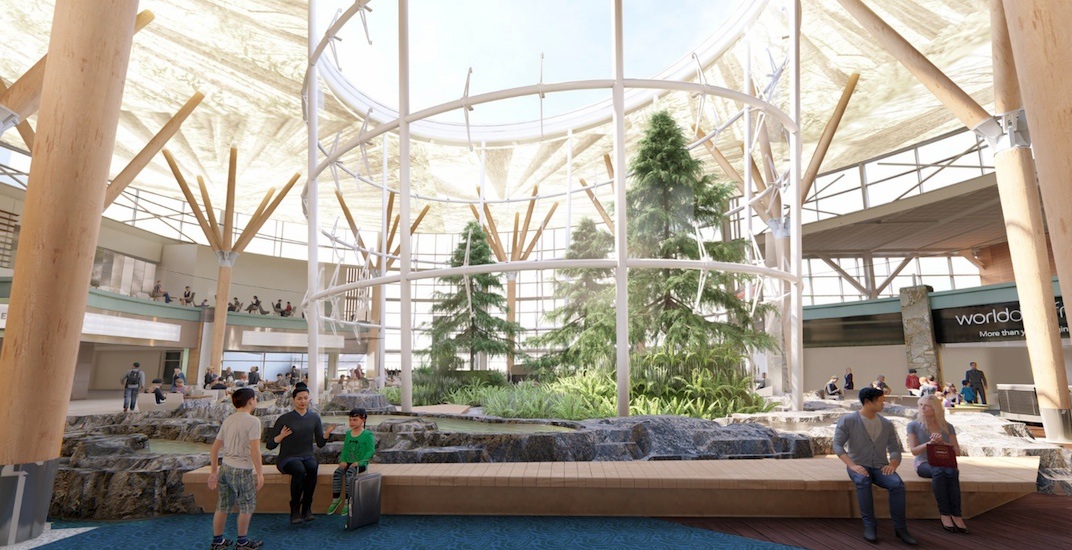
Original Vision for Indoor Forest via Architectural Render (Source: Vancouver Airport Authority)
Support Structure – An Overview
The frame support of the atrium was via steel with ten vertical steel columns forming the basis of the atrium and three levels of horizontal round HSS welded to the columns to connect them.
Stella’s glass hardware fell into four product groups based on function.
- Hardware Group A – Ring Beam Fittings
- Hardware Group B – Vertical Column Brackets
- Perimeter Channel (PC3710) affixed glass to floor and roof opening
- Custom Door Support Hardware on glass vestibule allowing access to indoor forest
-
This project overview will focus on how the first two hardware groups were designed and created
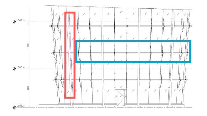
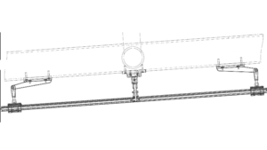
Atrium Elevation View Demonstrating Structural Support. Ring Beam Fittings (Group A) outlined in blue. Vertical Column Brackets (Group B) outlined in red. (Source/copyright: Stella Custom Glass Hardware Inc.)
Hardware Group A – Ring Beam Fittings
Fittings were to be attached to HSS ring beam via a tube clamp assembly with deadload tabs that offered on-site adjustability. The Center Edge Support was very adjustable offering in/out and vertical adjustability. Arms and tabs also swivelled to accommodate varying IGU facets.
As the project progressed, it was discovered via engineering and discussions with the architect and glazing contractor that while the adjustability was desired in concept, we could be more strategic about where adjustability was placed to achieve higher loading capabilities where needed as well as making them more installer-friendly.
Specific changes to original product design included:
Arm connection to HSS clamp
- Original design had four screws to affix each arm to the clamp around the HSS. After calculations and an FEA analysis, we determined that the high wind loads on the long fins warranted a weld connection instead of fasteners.
- This change to weld versus fastener connection made the connection more rigid. Now it had one large integrated weld connection from the inside of the ring that looked cleaner with fewer parts. Due to the reduced part count, there were on-site labour and manufacturing savings.
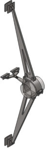
Original Proposed Design of Ring Beam Fitting. Demonstrates features such as A) tube clamp assembly with deadload tabs and B) much in/out adjustability on centre support. (Source/copyright: Stella Custom Glass Hardware Inc)
Centre connection on fin
- In the original design, we envisioned a great need for adjustability and articulation at the centre element due to the facetted glass. As the design and engineering evolved, it was determined that the glass was moving too much. The centre pivoting hardware was replaced with more rigid “spider”-influenced hardware.
- High loads at the centre connection also required higher loading capabilities. With our detailed FEA analysis, we pinpointed where additional loads were and selectively manufactured those hardware elements in a high-strength 2205 duplex steel. By keeping these changes to the yoke and “spider” only, we were able to meet loads discovered during the design process without a cost increase in the overall design.
- With the centre connection more rigid, we redesigned the top and bottom fin “arms” with more adjustability by adding a rod and clevis arrangement to accommodate the glass out of plane. The improved adjustability was huge at +/- 20mm at the top and bottom with +/- 10mm in the middle ledge.
Hardware Group B – Vertical Column Support Fittings
Key to the architects’ vision was a unifying look to hardware so as not to distract from the glass-enclosed indoor forest; they envisioned the steel “fins” on the ring beams to be aesthetically similar to the support on the vertical steel column. The resulting Stella hardware was a top & bottom fin and a stand-off in the middle that struck a balance between aesthetic and practicality.
Original Proposed Design of Vertical Column Support. Aesthetic is similar to ring beam fittings on project. Features top and bottom fin with a stand-off in middle for the perfect balance of practical and minimal aesthetic. (Source/copyright: Stella Custom Glass Hardware Inc)
On-Site – Installation Process
Collaboration with the entire project team from the early days of design made this project a success. With the project’s glazing partner, Flynn, we kept the ease of installation in fitting the glass and hardware at the forefront.
The Power of Collaboration To Reduce Labour Install Hours
The connection of the 60 ring beam “fins” to the round HSS steel support was originally planned to be connected via clamp connection/friction; as the project progressed, concerns about the fittings’ potential rotation grew.
Collectively, it was decided to place shear pins on the ring clamp (two on the top and two on the bottom of each collar). This changed the mounting of collars to a shear connection instead of a friction-clamped connection.
To expedite the installation process, we created several different specialized installation tools for this project.
Based on Flynn feedback, we created a custom pilot hole tool to fit the M16 hole for shear pins. Installers were able to mark the shear pin location using the tool, move the fitting slightly to drill the pin location fully, and then move the fin back to the location for the final install. The complex pre-work made the actual installation much easier as once the four shear pins were tightened, the hardware was in.
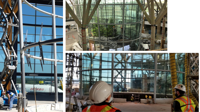
Compilation of Site Photos Showing Various Stages of Construction (Source: Flynn Group of Companies and Stella Custom Glass Hardware Inc)
On-Site Scanning
Multiple stages of 3D scanning greatly aided this project’s success. Flynn scanned the glazing portion of the project many times.
As the scanning identified potential issues, Flynn pushed for a multi-scenario install plan. They questioned how to adjust hardware if glass didn’t fit in various locations. We worked through adjustability limits in hardware and potential solutions if the glass on-site was out by more than the limits. We created actions plans for modifying our hardware on the fly to deal with various potential scenarios on site.
In reality, with all the analysis done in conjunction with scanning, there were minimal hardware modifications needed to meet site conditions – a success!
Result
With the glazing complete in Fall 2019, this 3-story glass atrium is an impressive sight. Unfortunately, while this expansion was due to open in 2020, COVID-19 postponed these plans until February 2021.
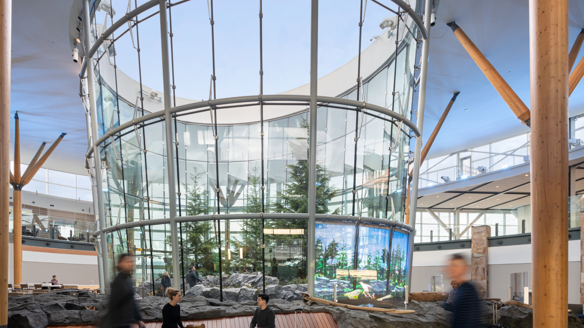
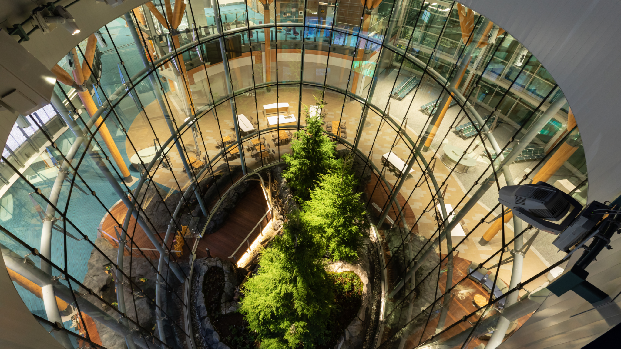
YVR Atrium Complete (Source/Copyright: Ema Peter Photography)
Project Team
Extensive collaboration and a skilled project team made this complex project possible. Open communication was key between all parties.
- Architect – Kasian
- Glazing Contractor – Flynn
- Structural Engineer – Bush Bohlman & Partners LLP
- General Contractor – PCL Constructors Westcoast Inc.
- Client/Owner – Vancouver International Airport